Flaming P'nut
History The RI/SME Sumo matches involved large (hundreds of pounds) robots on a five foot diameter ring. The strategy was simple: blast straight ahead and push anything out of the way. Our Explorer Post’s Sumo competitors always used Peg Perego motors and drive trains. Control was simple with micro switches and relays to control the motors. The chassis was plywood and body was aluminum. Four 6 Volt gel cells provided the power. For the 2002 SME competition the rules changed. The Sumo circle was extended to 16 feet diameter and the competitors initial start position was determined by the throw of a dice with six specified possibilities. While one group of kids worked on a new chassis, we developed the electronics based on our Sticky and Runt (Exhume) Sumo Robots. The Parallax BS2sx was used for control along with the software from Sticky with minor modifications for the different dynamics of the larger robot. Flaming P’nut had a problem at the 2002 RI/SME competition. See the first H Bridge below. For the 2003 RI/SME competition, Flaming P’nut dominated the 150 pound high school class. In 2004 the RI/SME was replaced by the Robotics and Technology Invitational organized by the Ohio Technology Organization. Flaming P'nut continued to dominate the 150 pound class. |
| Batteries The first problem that we faced was the multiple six Volt batteries in the Sumo. Each motor was likely to require 10 amperes of current and the battery needed to provide power for up to two 3 minute rounds. The existing 12 Volt 7 A-Hr, and double 6 Volt 12.7 A-Hr batteries were not capable of providing the power needed. A 12 Volt 18 A-Hr battery was close, but was barely adequate. A new 12 Volt 20 A-Hr battery proved to be much more capable of providing the needed power. Four Panasonic LC-X1220P batteries and two automotive battery chargers were purchased. These batteries have proven to be adequate for our needs. One battery powers all motors and electronics. |
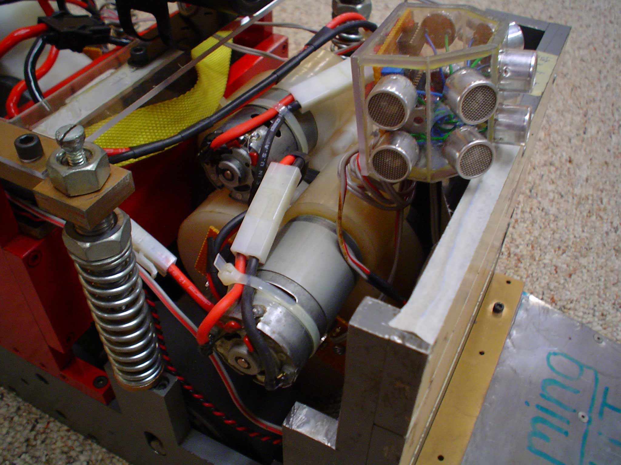
 Sensors Five IR proximity sensors were used on the front of Flaming P’nut. Each sensor covered approximately 15 degrees width, so the five covered about 75 degrees. Panasonic PNA4612MOOYB detectors and Fairchild QEC113 IR LEDs were used. Since the LEDs were being driven well beyond their rated capacity, an array of four LEDs was used for each sensor. An adjustable Voltage regulator providing power to the LEDs was used as a sensor distance adjustment.
No line sensors are used. Sensors Five IR proximity sensors were used on the front of Flaming P’nut. Each sensor covered approximately 15 degrees width, so the five covered about 75 degrees. Panasonic PNA4612MOOYB detectors and Fairchild QEC113 IR LEDs were used. Since the LEDs were being driven well beyond their rated capacity, an array of four LEDs was used for each sensor. An adjustable Voltage regulator providing power to the LEDs was used as a sensor distance adjustment.
No line sensors are used. |
 For 2002 the proximity sensors were set to five feet of range. This was very effective, but it was noted that the far right sensor and the right-center sensor produced considerably more range than the other three. For 2003 the detectors were replaced with Panasonic PNA4602M and some LEDs were removed so that all sensors had the same range. For 2003 the proximity sensors were set to four feet of range and were still very effective. For 2002 the proximity sensors were set to five feet of range. This was very effective, but it was noted that the far right sensor and the right-center sensor produced considerably more range than the other three. For 2003 the detectors were replaced with Panasonic PNA4602M and some LEDs were removed so that all sensors had the same range. For 2003 the proximity sensors were set to four feet of range and were still very effective. |
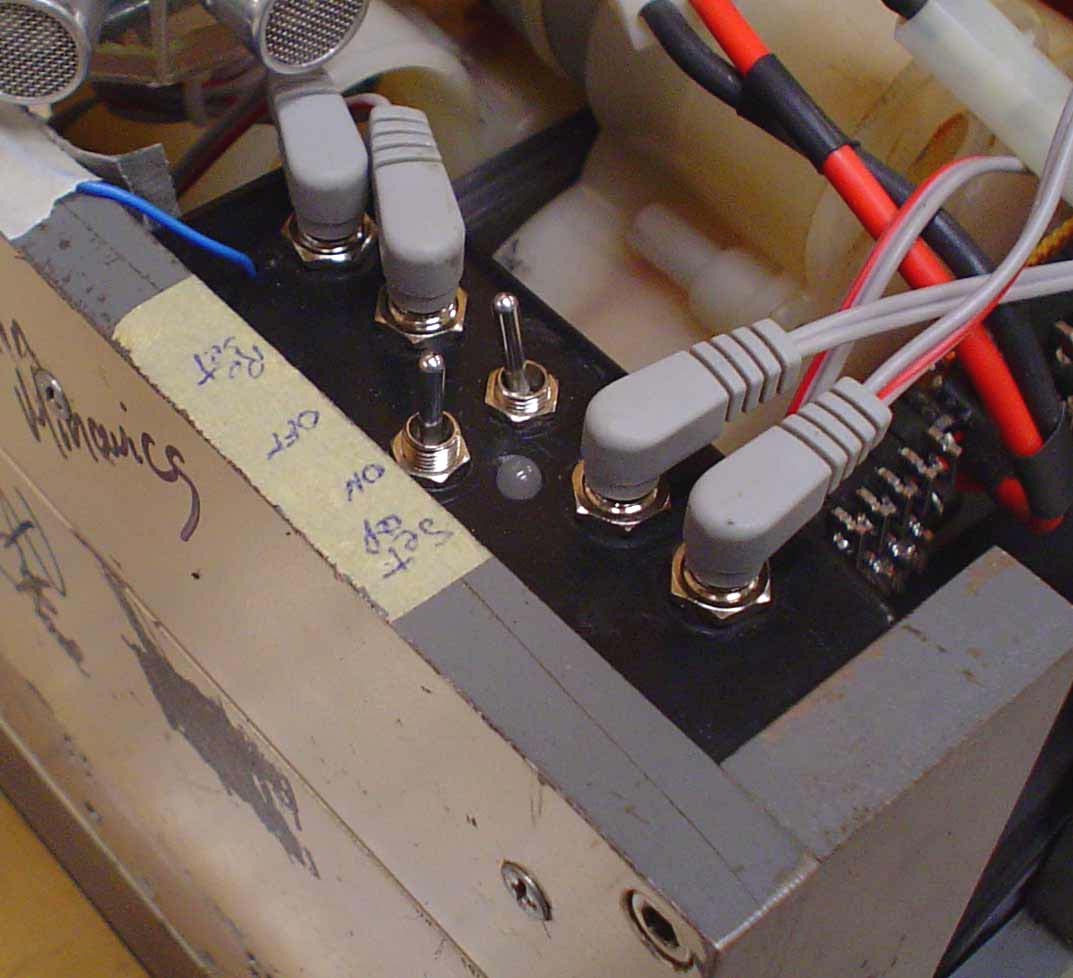
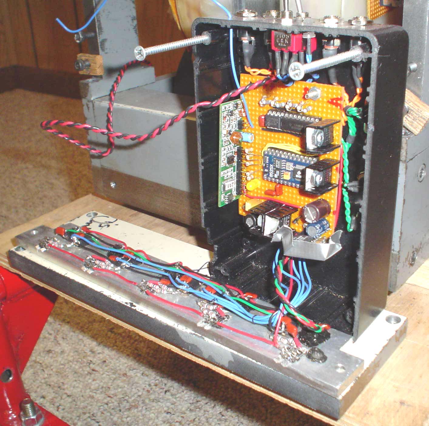
The control circuitry is housed in a plastic box bolted behind the front steel face. The top of the plastic box has the two starting toggle switches and connectors for the four motor drive boards. The rear of the box has the RS232 connection and two switched 12 volt outputs.
|
| The Parallax BS2SX has eight program slots (numbered 0 to 7). The present software for Flaming P’nut used four of the slots. The four programs cover four separate functional areas. Program slot 0 is the main start-up program called 2004Sumo.BSX. The main function of 2004Sumo.BSX is to determine whether to immediately attack or go into one of the start routines. It’s main input is the center-off toggle switch on top of the control box. 2004Sumo.BSX also runs the IR LED sensors and indicates their condition via the Red/Green LED on the control Box. Program slot 1 program, Start_Patterns.BSX runs the initial start routines. The main inputs to Start_Patterns.BSX are RAM and EEPROM stored variables from 2004SUMO.BSX. The stored variable tells Start_Patterns.BSX which start routine to run and whether to run the routine to the right or left. Program slot 2 contains the main program called SearchDestroy.BSX. This is the main program that looks for the opponent and attacks when anything is detected. There are several “What Ifs” programmed in to take unique evasive action based on previous year’s experience. The last program in program slot 3 is Remote_Control.BSX. This is just a demonstrator program that uses the “Kill Switch” inputs to tell the robot to go forward, turn right, turn left, or backup. |
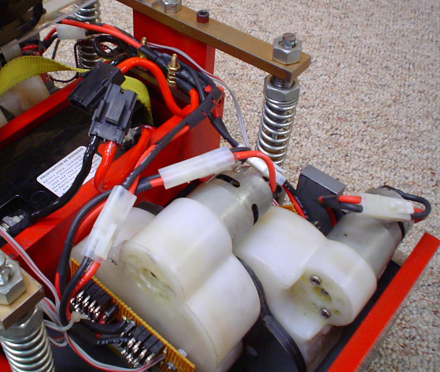
 Wiring Molex Waldom Mini-Fit, Sr. connectors (rated at 50 Amperes) is used with 8 gauge wire for the battery connections. Molex Waldom “Toy Car” Battery Connectors with 12 gauge silicone coated wire are used on each individual H Bridge and motor. The plugs allow modular replacement of the battery, H bridges, or motors. There are no fuses, circuit breakers, or switches between the battery and the motors. Wiring Molex Waldom Mini-Fit, Sr. connectors (rated at 50 Amperes) is used with 8 gauge wire for the battery connections. Molex Waldom “Toy Car” Battery Connectors with 12 gauge silicone coated wire are used on each individual H Bridge and motor. The plugs allow modular replacement of the battery, H bridges, or motors. There are no fuses, circuit breakers, or switches between the battery and the motors. |
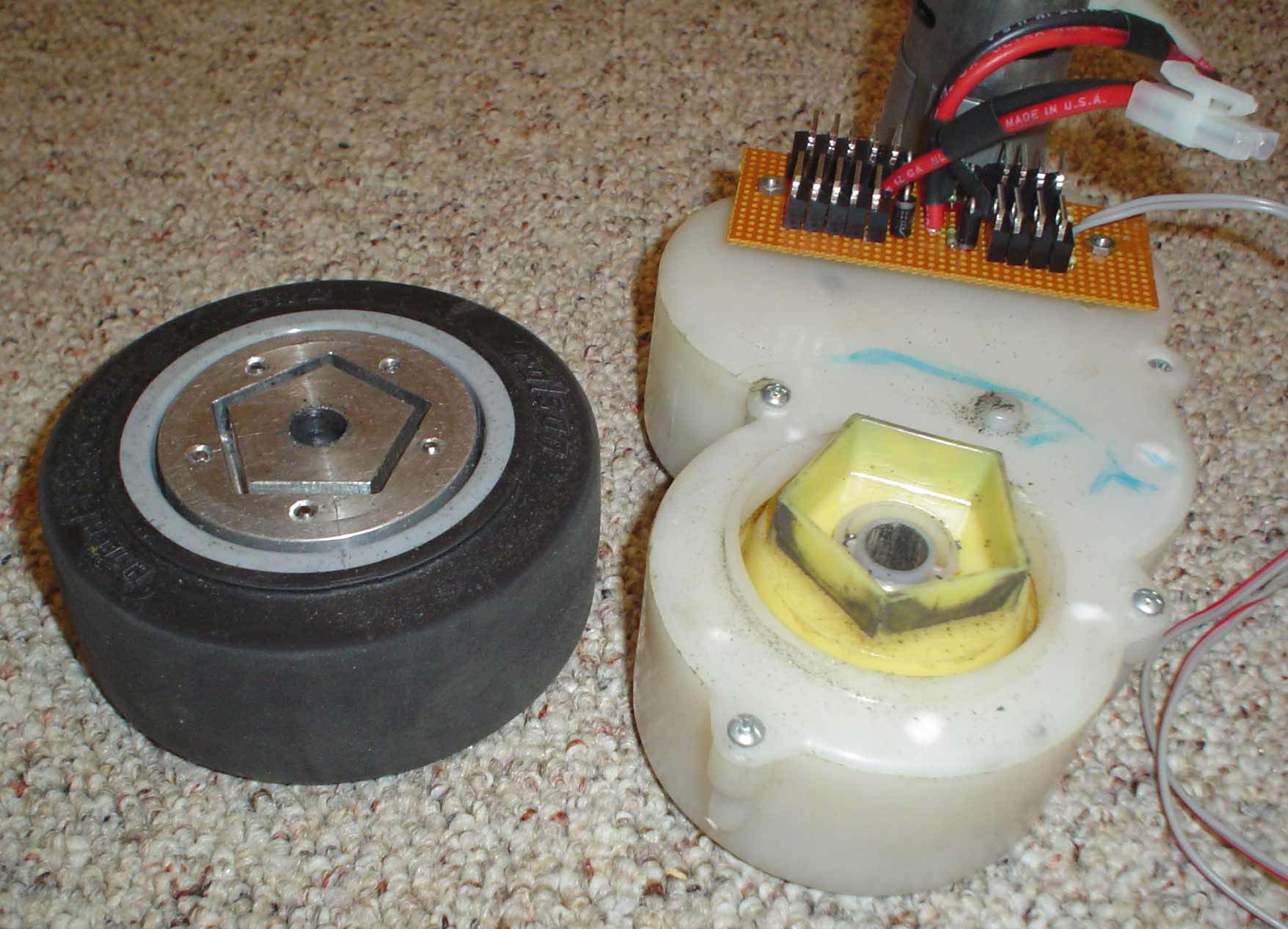
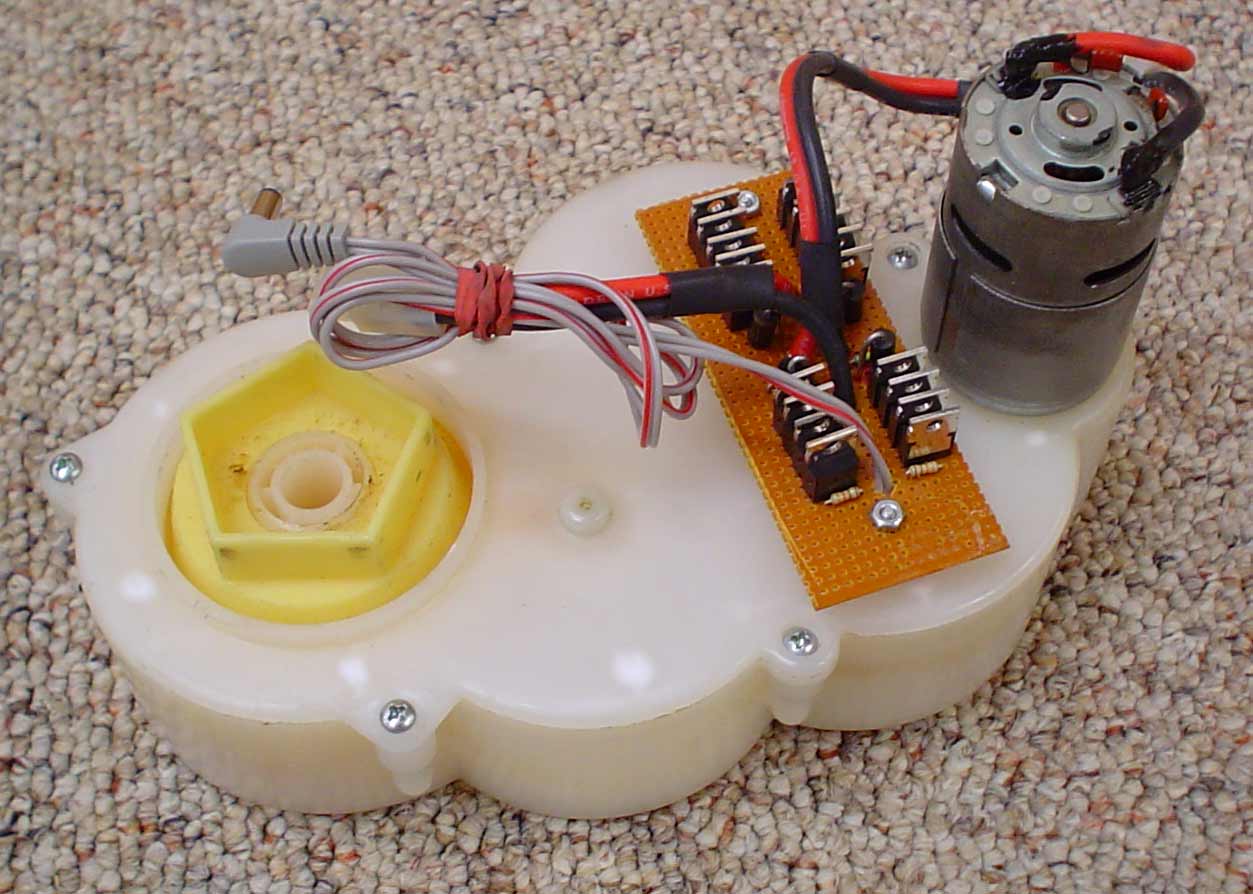
Six gearboxes are used. There are four in Flaming P’nut and two spare with spare H bridges and motors. We have never had any gearbox problems. |
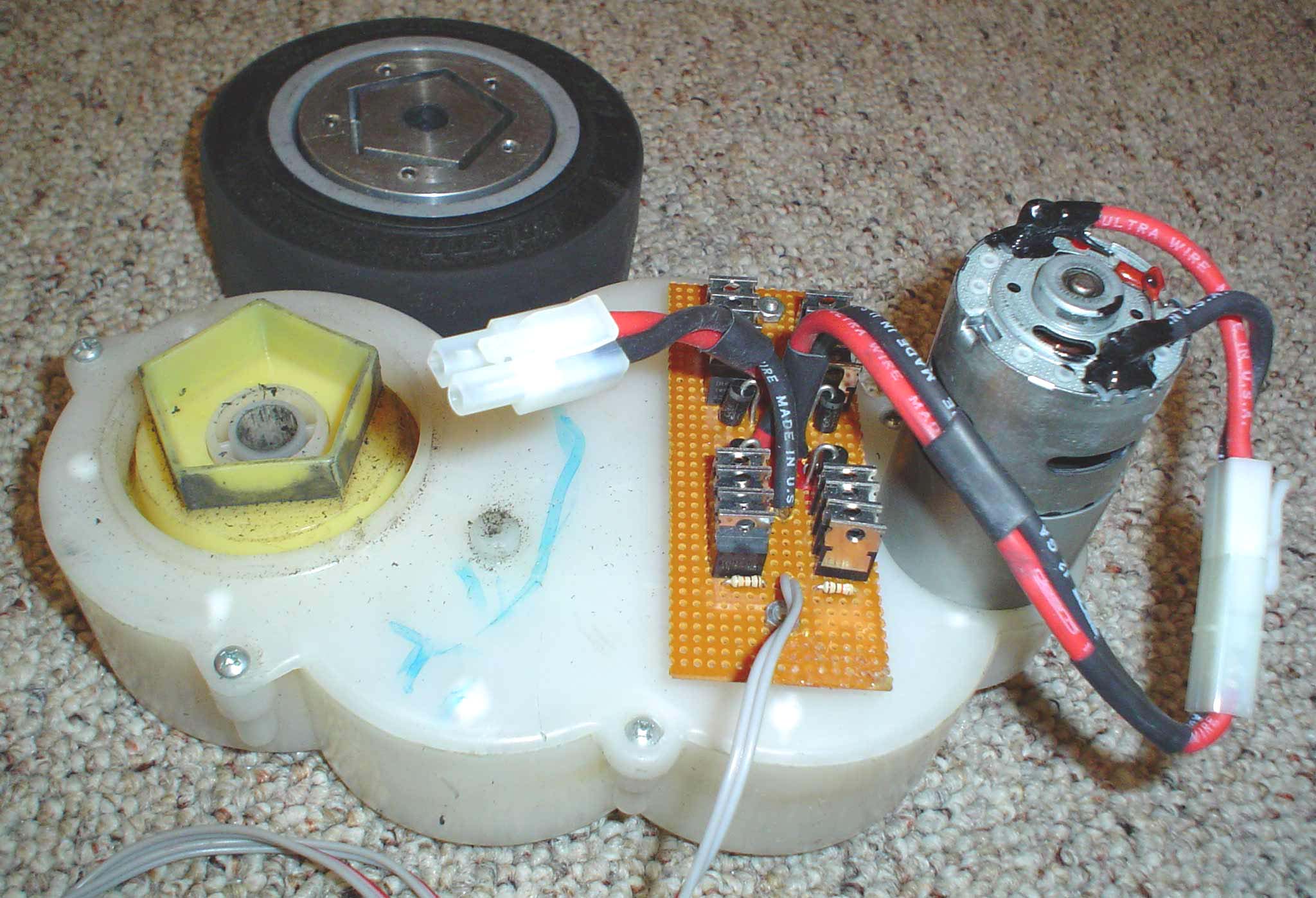 Motors The Peg Perego motors are RS-775SF type and are not modified. These appear to be similar to the Mabuchi RS-775VC motors that are rated at 40 to 200 Watts at 6 to 20 Volts. The motors are not modified. When Flaming P’nut hits top speed, the motors are turning 16,300 rpm. The motors are presently running on 12 Volts. There is the possibility of some performance improvement here Motors The Peg Perego motors are RS-775SF type and are not modified. These appear to be similar to the Mabuchi RS-775VC motors that are rated at 40 to 200 Watts at 6 to 20 Volts. The motors are not modified. When Flaming P’nut hits top speed, the motors are turning 16,300 rpm. The motors are presently running on 12 Volts. There is the possibility of some performance improvement here |
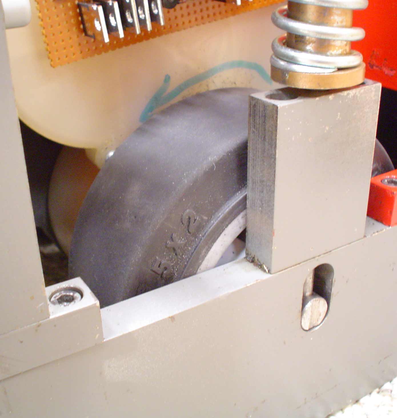
For 2003 the iron wheels were replaced by Colson Performa Rubber Wheels. Part of the wheels had to be machined off to fit the hub. The wheels are held to the hubs with five 3/16 inch dowels passing through the wheels and hubs parallel to the axle. |
H Bridge First Design Two FETs per H bridge leg were used. The positive side was IRF9540N FETs and the negative side was IRF540N FETs. The FETs were driven by the output of an optical isolator. SR504CT Schottky diodes were used to suppress voltage spikes. The BS2SX processor generated standard servo pulse width (1.0 msec to 2.0 msec) signals to standard servo electronics. The servo electronics drove the optical isolators instead of the normal servo motor. This resulted in a Pulse Width Modulated drive at a frequency of 50 Hertz. The IRF9540N and IRF540N were deemed sufficient to handle the 10 ampere maximum load of the motors without heat sinks. During the third match of the 2002 event, Flaming P’nut locked up with another 150 pound robot and spun in a tight circle for about a minute. That proved too much for the right rear H bridge and two of the IRF9540Ns blew up in a big way. A redesign was necessary. |
Driving five IRF4905 and four IRF3205 gates with an optical isolator seemed to be insufficient and the 50 Hertz PWM rate seemed slow. So, the Servo Electronics and optical isolators were replaced with a Pololu Dual Serial Motor Controller. The SN754410 could provide a substantial amount of gate drive current and the PIC created a PWM frequency of 600 Hertz. Also, the BS2SX programming was modified to initiate an escape routine if Flaming P’nut did the same thing too many times. |
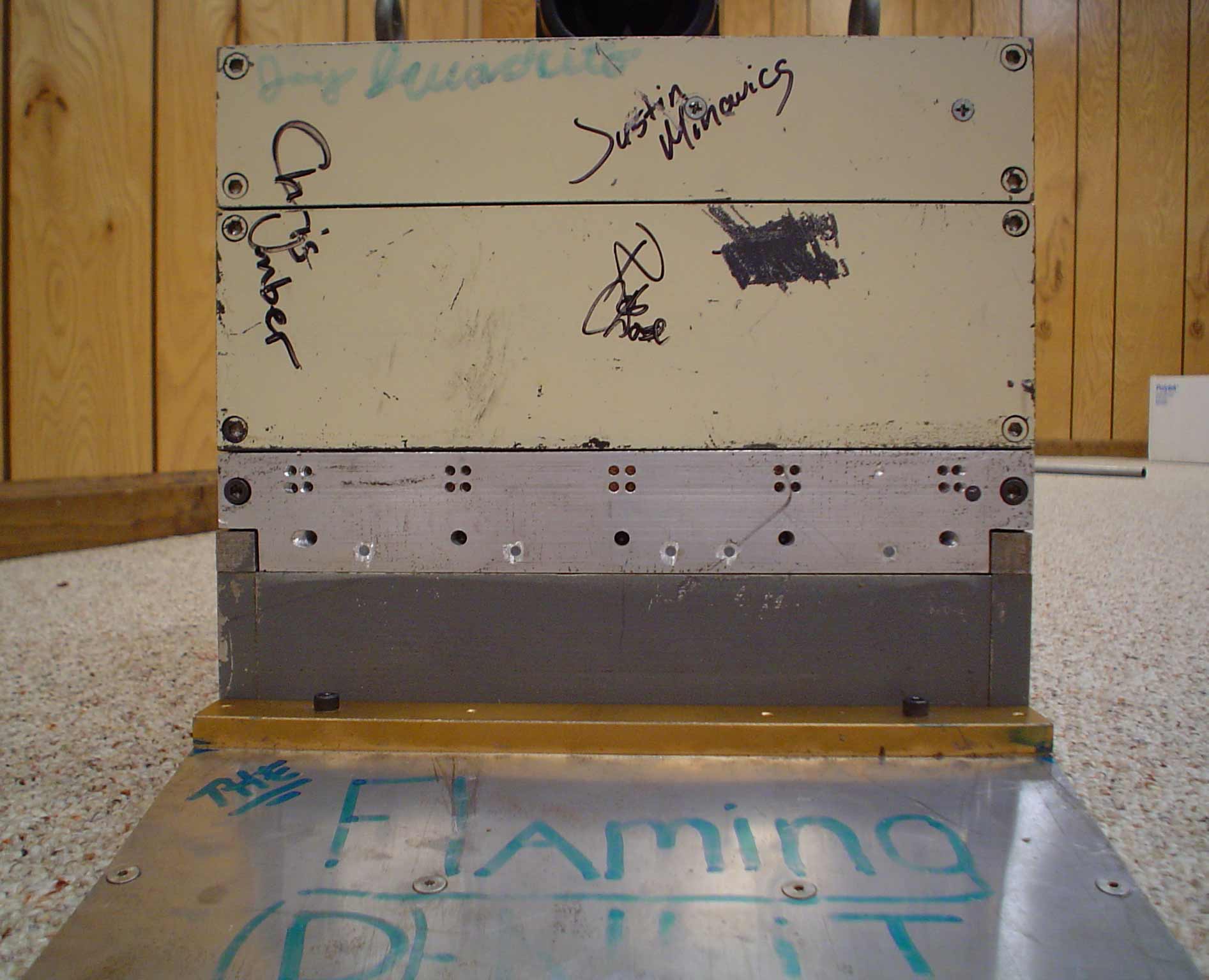
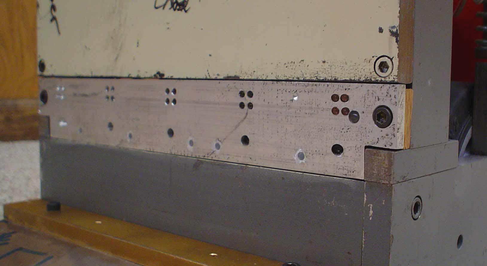
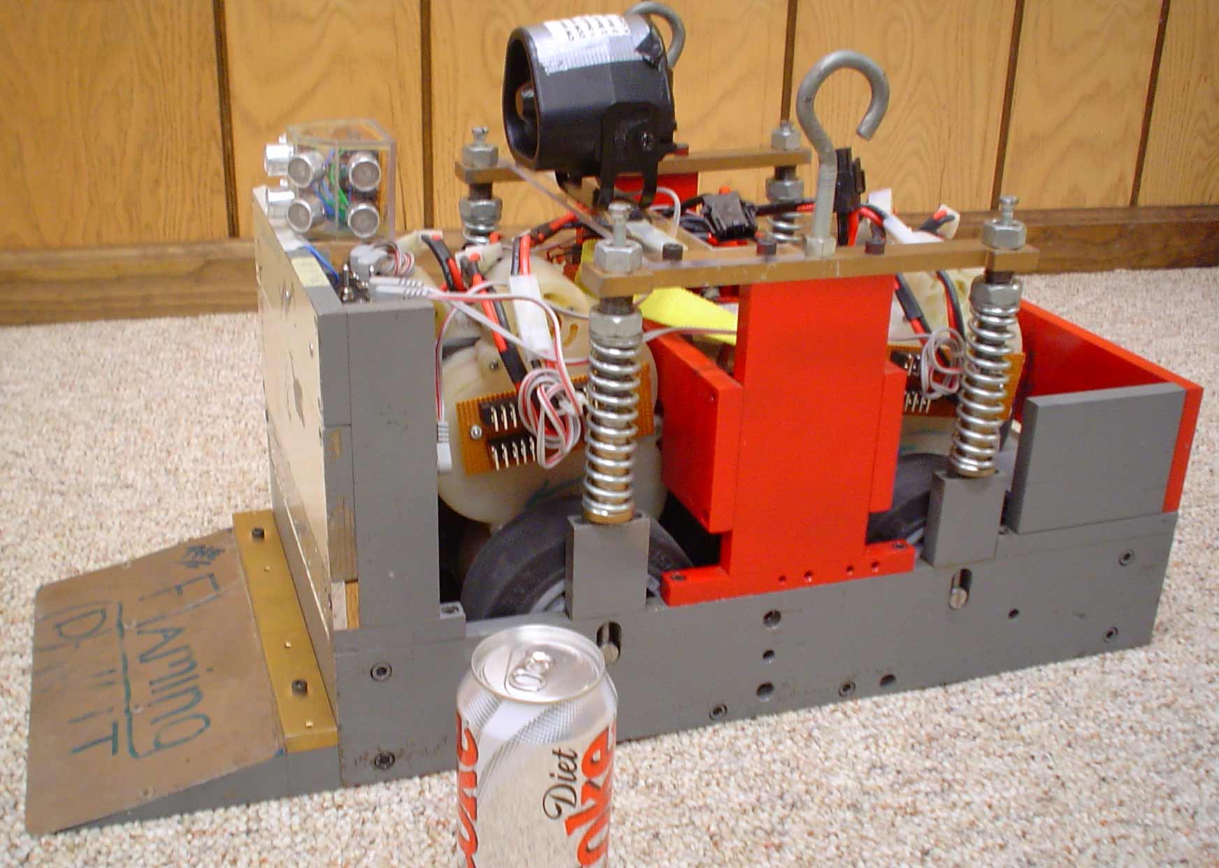 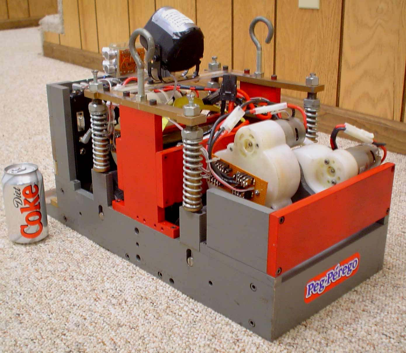 Chassis The chassis was designed to hold the four drive trains, one battery, sensors, and controls and result in a total weight of 150 pounds. That design exercise resulted in a 102 pound chassis comprised primarily of ½ inch steel. Chassis The chassis was designed to hold the four drive trains, one battery, sensors, and controls and result in a total weight of 150 pounds. That design exercise resulted in a 102 pound chassis comprised primarily of ½ inch steel. |
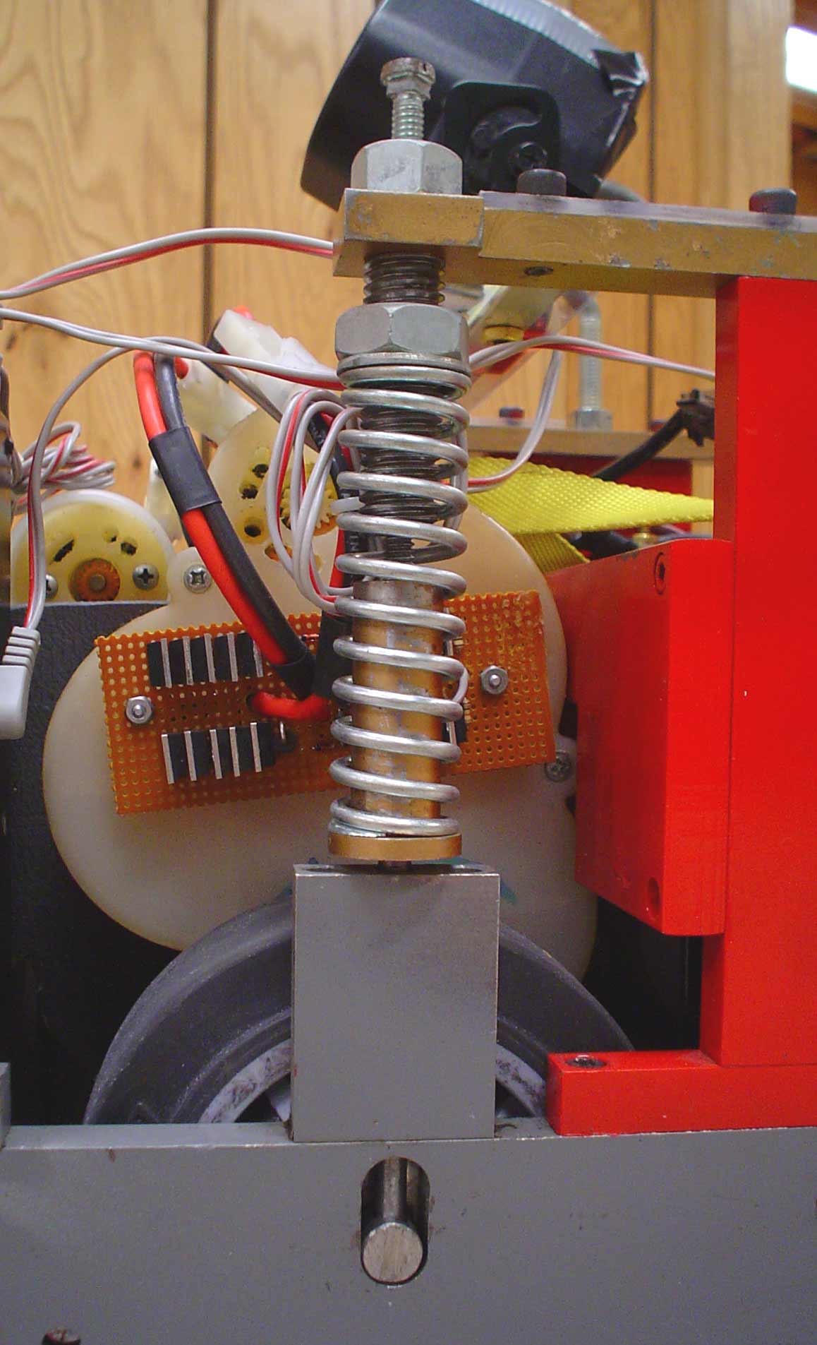 Suspension Previous Sumo robots lifted their front tires when pushing hard on an opponent. The suspension was designed to keep the front tires on the ground and furnishing thrust in most heavy pushing situations. The spring adjustment controls the amount of weight transfer during heavy pushing. We do not have sufficient experience to test the effectiveness of the suspension. The four screws on top of the suspension units control the height of the chassis off of the ground. They have a range of about 3/8 inch clearance maximum down to no clearance at all. This range of adjustment has come in very handy many times. Suspension Previous Sumo robots lifted their front tires when pushing hard on an opponent. The suspension was designed to keep the front tires on the ground and furnishing thrust in most heavy pushing situations. The spring adjustment controls the amount of weight transfer during heavy pushing. We do not have sufficient experience to test the effectiveness of the suspension. The four screws on top of the suspension units control the height of the chassis off of the ground. They have a range of about 3/8 inch clearance maximum down to no clearance at all. This range of adjustment has come in very handy many times. |
The 2002 version of Flaming P’nut had, as a starting option, as IR television remote control. That control would both start the match and select the start routine and direction. The remote start was not allowed to be used even though the rules specifically allowed “a remote off/on switch”. The rules have since been changed to allow only remote off switches. |
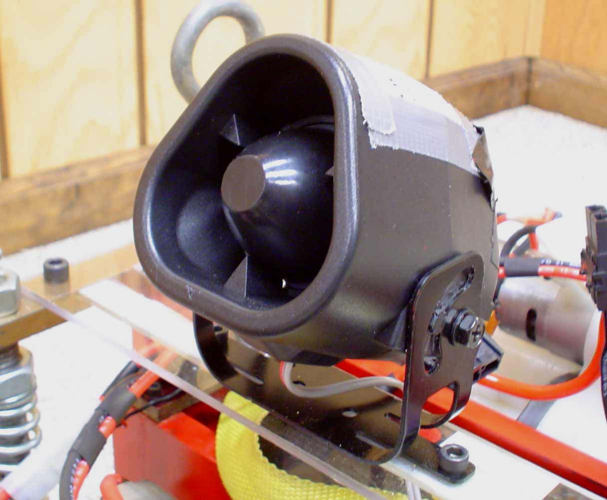 Alarm As a novelty and to increase crowd appeal, an alarm was added. The alarm is initiated whenever four of the five IR sensors see something…basically after Flaming P'nut has “locked on” to the other robot. Since the Sumo matches were to be run in an ice hockey arena, the loudest car alarm siren was used. The alarm could be heard everywhere in the arena and anyone within ten feet of Flaming P’nut would describe the experience as “PAINFUL”. Alarm As a novelty and to increase crowd appeal, an alarm was added. The alarm is initiated whenever four of the five IR sensors see something…basically after Flaming P'nut has “locked on” to the other robot. Since the Sumo matches were to be run in an ice hockey arena, the loudest car alarm siren was used. The alarm could be heard everywhere in the arena and anyone within ten feet of Flaming P’nut would describe the experience as “PAINFUL”. |
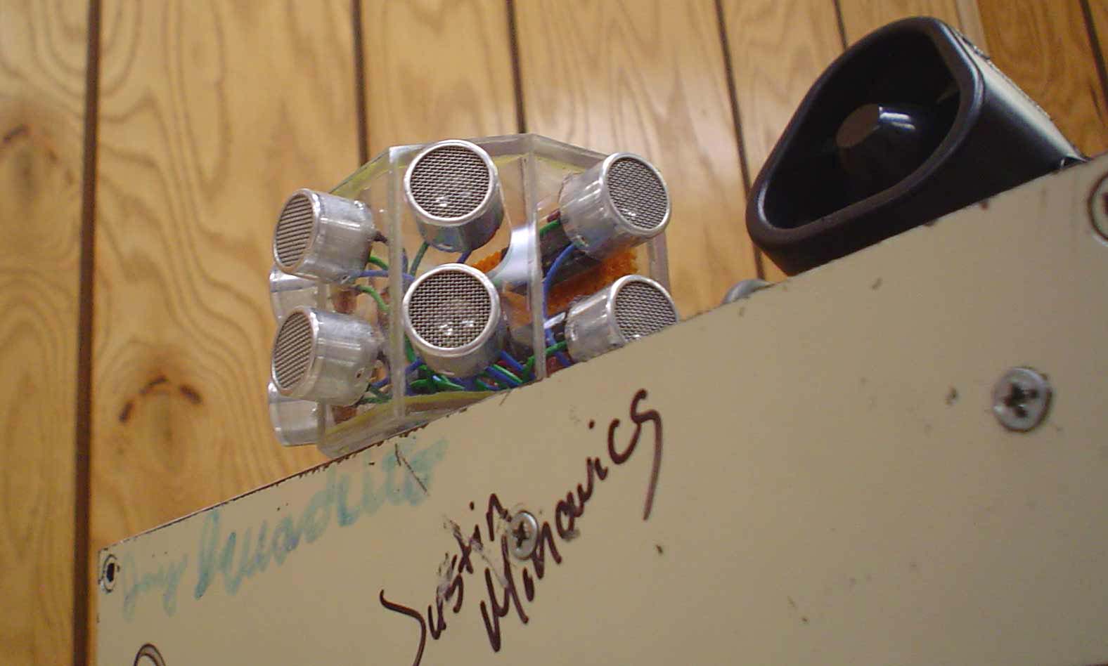 Sonar Jammers When Devantech Ltd. first introduced their SRF04 Ultrasonic Range Finder, it was obvious that many Sumo contestants would use them for opponent detection. The sonar unit seemed to be too easy to jam, so a jammer was developed. It consisted of a 555 type timer producing a 38 KHz signal which drove two SN754410 chips and then eight sonar transducers. The precise frequency of the 555 timer was adjusted to give the biggest impact on the SRF04 unit. Also, the jammer is under the control of the BS2SX, turning on only after the bout starts. Sonar Jammers When Devantech Ltd. first introduced their SRF04 Ultrasonic Range Finder, it was obvious that many Sumo contestants would use them for opponent detection. The sonar unit seemed to be too easy to jam, so a jammer was developed. It consisted of a 555 type timer producing a 38 KHz signal which drove two SN754410 chips and then eight sonar transducers. The precise frequency of the 555 timer was adjusted to give the biggest impact on the SRF04 unit. Also, the jammer is under the control of the BS2SX, turning on only after the bout starts. |
  Remote Kill Switch After the 2002 competition it was obvious that 150 pound robots with drive trains capable of ten to twenty miles per hour were dangerous. To reduce the danger the 2003 Flaming P’nut had a remote kill switch. A code hopping four channel remote control from Oatley Electronics was used to reduce the possibility of false kill signals. This arrangement proved to be very helpful and very reliable during the 2003 competition. Remote Kill Switch After the 2002 competition it was obvious that 150 pound robots with drive trains capable of ten to twenty miles per hour were dangerous. To reduce the danger the 2003 Flaming P’nut had a remote kill switch. A code hopping four channel remote control from Oatley Electronics was used to reduce the possibility of false kill signals. This arrangement proved to be very helpful and very reliable during the 2003 competition. |